Pipe Fitting Types
Select a fitting class, then click on any fitting type below to view its specifications and technical dimensional data.
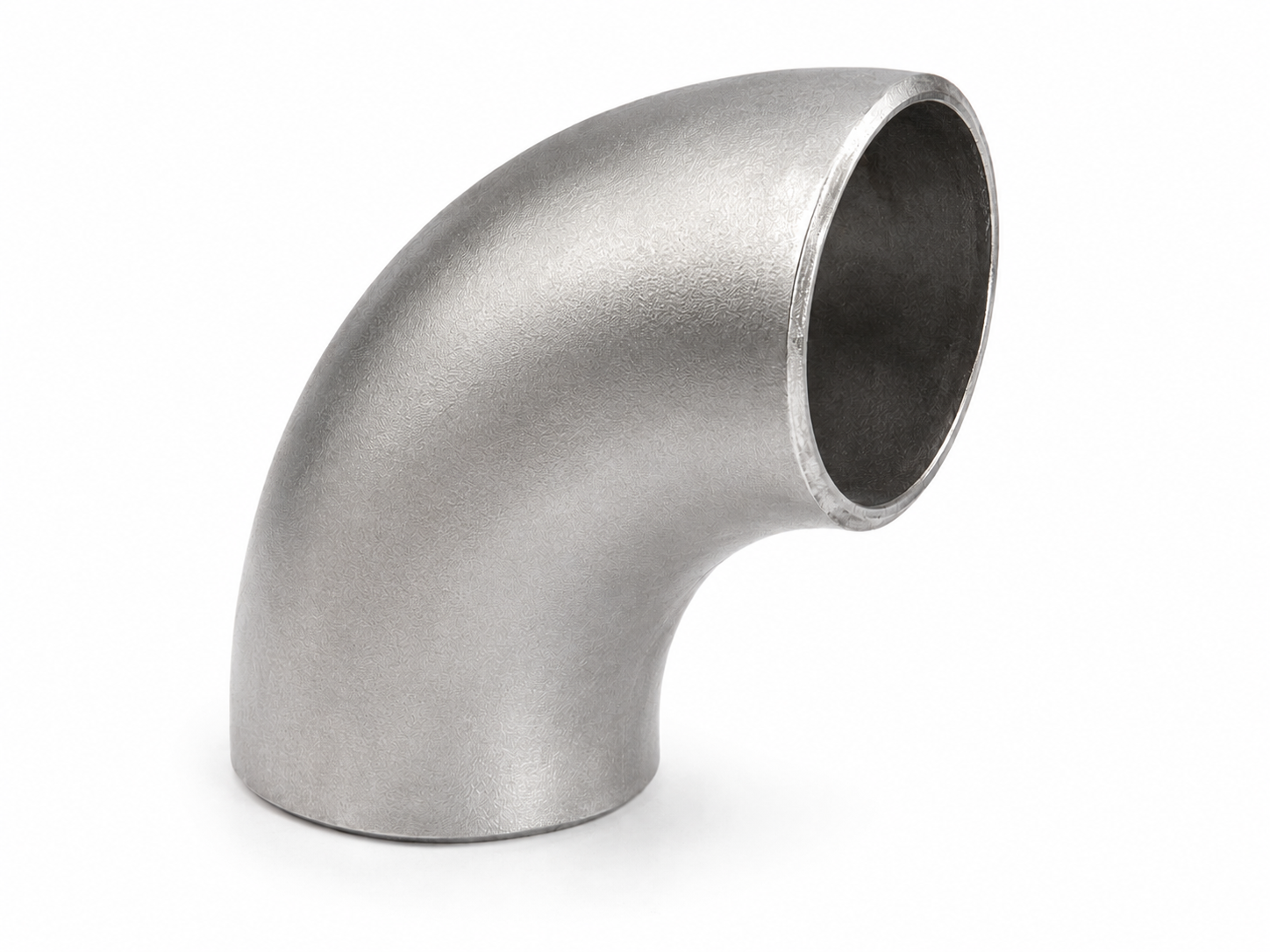
Long-radius (LR) elbows are the industry default, with centre-line radius (CLR) = 1.5 × NPS, giving smoother flow and lower pressure drop than short-radius. Available seamless or welded, in butt-weld ends per ASME B16.9.
| NPS | OD (mm) | CLR (mm) | F-to-F (mm) | SCH 40 Wall (mm) | Approx Wt (kg) |
|---|---|---|---|---|---|
| ½" | 21.3 | 38.1 | 38 | 2.77 | 0.03 |
| ¾" | 26.7 | 50.8 | 48 | 2.87 | 0.05 |
| 1" | 33.4 | 50.8 | 56 | 3.38 | 0.09 |
| 1¼" | 42.2 | 63.5 | 70 | 3.56 | 0.14 |
| 1½" | 48.3 | 76.2 | 86 | 3.68 | 0.20 |
| 2" | 60.3 | 76.2 | 105 | 3.91 | 0.34 |
| 2½" | 73.0 | 101.6 | 124 | 5.16 | 0.54 |
| 3" | 88.9 | 114.3 | 146 | 5.49 | 0.87 |
| 4" | 114.3 | 152.4 | 190 | 6.02 | 1.62 |
| 5" | 141.3 | 190.5 | 238 | 6.55 | 2.70 |
| 6" | 168.3 | 228.6 | 286 | 7.11 | 4.05 |
| 8" | 219.1 | 304.8 | 381 | 8.18 | 8.16 |
| 10" | 273.1 | 381.0 | 470 | 9.27 | 14.7 |
| 12" | 323.9 | 457.2 | 559 | 9.53 | 22.9 |
| 14" | 355.6 | 533.4 | 635 | 9.53 | 33.1 |
| 16" | 406.4 | 609.6 | 724 | 9.53 | 48.4 |
| 18" | 457.2 | 685.8 | 813 | 9.53 | 68.0 |
| 20" | 508.0 | 762.0 | 902 | 9.53 | 92.4 |
| 24" | 610.0 | 914.4 | 1067 | 9.53 | 155.8 |
Source: ASME B16.9. CLR = Centre Line Radius. F-to-F = Face to Face dimension. Weights are approximate for SCH 40 carbon steel (ASTM A234 WPB). Other schedules available.
Short-radius (SR) elbows, with centre-line radius (CLR) = 1.0 × NPS, are used where space is limited and a sharper direction change is acceptable. They give a higher pressure drop than long-radius. Available seamless or welded, in butt-weld ends per ASME B16.9.
| NPS | OD (mm) | CLR (mm) | Centre-to-End A (mm) |
|---|---|---|---|
| 1" | 33.4 | 25.4 | 25 |
| 1¼" | 42.2 | 31.8 | 32 |
| 1½" | 48.3 | 38.1 | 38 |
| 2" | 60.3 | 50.8 | 51 |
| 2½" | 73.0 | 63.5 | 64 |
| 3" | 88.9 | 76.2 | 76 |
| 3½" | 101.6 | 88.9 | 89 |
| 4" | 114.3 | 101.6 | 102 |
| 5" | 141.3 | 127.0 | 127 |
| 6" | 168.3 | 152.4 | 152 |
| 8" | 219.1 | 203.2 | 203 |
| 10" | 273.0 | 254.0 | 254 |
| 12" | 323.8 | 304.8 | 305 |
| 14" | 355.6 | 355.6 | 356 |
| 16" | 406.4 | 406.4 | 406 |
| 18" | 457.0 | 457.2 | 457 |
| 20" | 508.0 | 508.0 | 508 |
| 24" | 610.0 | 609.6 | 610 |
Source: ASME B16.9. CLR = 1.0×NPS for short radius (vs. 1.5×NPS for long radius). A = Centre-to-End. Short-radius elbows are standard from NPS 1" up to 24"; below 1" NPS, long-radius is used as the SR pattern is not commonly forged. SR gives a sharper direction change but a higher pressure drop than LR.
45° elbows change line direction by 45 degrees with a lower pressure drop than a 90° bend, commonly used for offset routing around obstructions. Supplied long-radius as standard, in butt-weld ends per ASME B16.9.
| NPS | OD (mm) | Centre-to-End B (mm) | SCH 40 Wall (mm) | Approx Wt (kg) |
|---|---|---|---|---|
| ½" | 21.3 | 16 | 2.77 | 0.02 |
| ¾" | 26.7 | 19 | 2.87 | 0.03 |
| 1" | 33.4 | 22 | 3.38 | 0.05 |
| 1¼" | 42.2 | 25 | 3.56 | 0.08 |
| 1½" | 48.3 | 29 | 3.68 | 0.11 |
| 2" | 60.3 | 35 | 3.91 | 0.19 |
| 2½" | 73.0 | 44 | 5.16 | 0.30 |
| 3" | 88.9 | 51 | 5.49 | 0.48 |
| 4" | 114.3 | 64 | 6.02 | 0.89 |
| 5" | 141.3 | 79 | 6.55 | 1.49 |
| 6" | 168.3 | 95 | 7.11 | 2.23 |
| 8" | 219.1 | 127 | 8.18 | 4.49 |
| 10" | 273.0 | 159 | 9.27 | 8.09 |
| 12" | 323.8 | 190 | 9.53 | 12.6 |
| 14" | 355.6 | 222 | 9.53 | 18.2 |
| 16" | 406.4 | 254 | 9.53 | 26.6 |
| 18" | 457.0 | 286 | 9.53 | 37.4 |
| 20" | 508.0 | 318 | 9.53 | 50.8 |
| 24" | 610.0 | 381 | 9.53 | 85.7 |
Source: ASME B16.9 Table 3. B = Centre-to-End dimension for 45° LR elbow. Weights are approximate for SCH 40 carbon steel (ASTM A234 WPB), taken as ~55% of the equivalent 90° LR elbow weight.
Equal (straight) tees have a branch outlet the same bore as the run pipe, used for symmetric three-way branch connections. Butt-weld ends per ASME B16.9.
| NPS | OD (mm) | Centre-to-End Run C (mm) | Centre-to-End Outlet M (mm) | SCH 40 Wall (mm) |
|---|---|---|---|---|
| ½" | 21.3 | 25 | 25 | 2.77 |
| ¾" | 26.7 | 29 | 29 | 2.87 |
| 1" | 33.4 | 38 | 38 | 3.38 |
| 1¼" | 42.2 | 48 | 48 | 3.56 |
| 1½" | 48.3 | 57 | 57 | 3.68 |
| 2" | 60.3 | 64 | 64 | 3.91 |
| 2½" | 73.0 | 76 | 76 | 5.16 |
| 3" | 88.9 | 86 | 86 | 5.49 |
| 4" | 114.3 | 105 | 105 | 6.02 |
| 5" | 141.3 | 124 | 124 | 6.55 |
| 6" | 168.3 | 143 | 143 | 7.11 |
| 8" | 219.1 | 178 | 178 | 8.18 |
| 10" | 273.0 | 216 | 216 | 9.27 |
| 12" | 323.8 | 254 | 254 | 9.53 |
| 14" | 355.6 | 279 | 279 | 9.53 |
| 16" | 406.4 | 305 | 305 | 9.53 |
| 18" | 457.0 | 343 | 343 | 9.53 |
| 20" | 508.0 | 381 | 381 | 9.53 |
| 24" | 610.0 | 432 | 432 | 9.53 |
Source: ASME B16.9 Table 8. C = Centre-to-End, Run. M = Centre-to-End, Outlet. Outlet dimension M for NPS 26 and larger is recommended but not mandatory per the standard.
Reducing tees have a branch outlet smaller than the run bore, used to split flow into a smaller-diameter branch line. Specified by run size × run size × branch size (e.g. 6"×6"×4").
| Run × Branch (NPS) | Run OD (mm) | Branch OD (mm) | Centre-to-End Run C (mm) | Centre-to-End Outlet M (mm) |
|---|---|---|---|---|
| ¾"×¾"×½" | 26.7 | 21.3 | 29 | 29 |
| 1"×1"×¾" | 33.4 | 26.7 | 38 | 38 |
| 1¼"×1¼"×1" | 42.2 | 33.4 | 48 | 48 |
| 1½"×1½"×1¼" | 48.3 | 42.2 | 57 | 57 |
| 2"×2"×1½" | 60.3 | 48.3 | 64 | 60 |
| 2½"×2½"×2" | 73.0 | 60.3 | 76 | 70 |
| 3"×3"×2½" | 88.9 | 73.0 | 86 | 83 |
| 3½"×3½"×3" | 101.6 | 88.9 | 95 | 92 |
| 4"×4"×3½" | 114.3 | 101.6 | 105 | 102 |
| 5"×5"×4" | 141.3 | 114.3 | 125 | 117 |
| 6"×6"×5" | 168.3 | 141.3 | 143 | 137 |
| 8"×8"×6" | 219.1 | 168.3 | 178 | 168 |
| 10"×10"×8" | 273.0 | 219.1 | 216 | 203 |
| 12"×12"×10" | 323.8 | 273.0 | 254 | 241 |
| 14"×14"×12" | 355.6 | 323.8 | 279 | 270 |
| 16"×16"×14" | 406.4 | 355.6 | 305 | 305 |
| 18"×18"×16" | 457.0 | 406.4 | 343 | 330 |
| 20"×20"×18" | 508.0 | 457.0 | 381 | 368 |
| 24"×24"×22" | 610.0 | 559.0 | 432 | 432 |
Source: ASME B16.9 Table 9. Table shows one common branch reduction per run size; every other run/branch combination in the ½"–48" range is also available — send your bill of materials for a full quote.
Concentric reducers change pipe size on a common centreline, used where the pipe run stays centred (e.g. vertical runs or pump suction lines away from air-pocket concerns).
| Large × Small (NPS) | OD Large End (mm) | OD Small End (mm) | Face-to-Face H (mm) |
|---|---|---|---|
| ¾"×½" | 26.7 | 21.3 | 38 |
| 1"×¾" | 33.4 | 26.7 | 51 |
| 1¼"×1" | 42.2 | 33.4 | 51 |
| 1½"×1¼" | 48.3 | 42.2 | 64 |
| 2"×1½" | 60.3 | 48.3 | 76 |
| 2½"×2" | 73.0 | 60.3 | 89 |
| 3"×2½" | 88.9 | 73.0 | 89 |
| 3½"×3" | 101.6 | 88.9 | 102 |
| 4"×3½" | 114.3 | 101.6 | 102 |
| 5"×4" | 141.3 | 114.3 | 127 |
| 6"×5" | 168.3 | 141.3 | 140 |
| 8"×6" | 219.1 | 168.3 | 152 |
| 10"×8" | 273.0 | 219.1 | 178 |
| 12"×10" | 323.8 | 273.0 | 203 |
| 14"×12" | 355.6 | 323.8 | 330 |
| 16"×14" | 406.4 | 355.6 | 356 |
| 18"×16" | 457.0 | 406.4 | 381 |
| 20"×18" | 508.0 | 457.0 | 508 |
| 24"×22" | 610.0 | 559.0 | 508 |
Source: ASME B16.9 Table 12. H = Overall Length (Face-to-Face). Table shows one common size reduction per large-end NPS; every other large/small combination in the ½"–48" range is also available on request. Eccentric reducers share the same H dimension per ASME B16.9.
Eccentric reducers change pipe size with one side flat, keeping either the top or bottom of the pipe level — used on pump suction lines to prevent air pockets or on supported horizontal runs.
| Large × Small (NPS) | OD Large End (mm) | OD Small End (mm) | Face-to-Face H (mm) |
|---|---|---|---|
| ¾"×½" | 26.7 | 21.3 | 38 |
| 1"×¾" | 33.4 | 26.7 | 51 |
| 1¼"×1" | 42.2 | 33.4 | 51 |
| 1½"×1¼" | 48.3 | 42.2 | 64 |
| 2"×1½" | 60.3 | 48.3 | 76 |
| 2½"×2" | 73.0 | 60.3 | 89 |
| 3"×2½" | 88.9 | 73.0 | 89 |
| 3½"×3" | 101.6 | 88.9 | 102 |
| 4"×3½" | 114.3 | 101.6 | 102 |
| 5"×4" | 141.3 | 114.3 | 127 |
| 6"×5" | 168.3 | 141.3 | 140 |
| 8"×6" | 219.1 | 168.3 | 152 |
| 10"×8" | 273.0 | 219.1 | 178 |
| 12"×10" | 323.8 | 273.0 | 203 |
| 14"×12" | 355.6 | 323.8 | 330 |
| 16"×14" | 406.4 | 355.6 | 356 |
| 18"×16" | 457.0 | 406.4 | 381 |
| 20"×18" | 508.0 | 457.0 | 508 |
| 24"×22" | 610.0 | 559.0 | 508 |
Source: ASME B16.9 Table 12. H = Overall Length; eccentric reducers use the same face-to-face dimension as concentric reducers, with the bore offset to one side instead of centred. Table shows one common size reduction per large-end NPS — other combinations available on request.
Pipe caps are dome-shaped end closures welded onto a pipe end to seal it off, used for line termination, testing points, or future tie-ins.
| NPS | OD (mm) | Length E (mm) | Approx Wt STD (kg) |
|---|---|---|---|
| ½" | 21.3 | 25 | — |
| ¾" | 26.7 | 25 | — |
| 1" | 33.4 | 38 | 0.09 |
| 1¼" | 42.2 | 38 | 0.14 |
| 1½" | 48.3 | 38 | 0.18 |
| 2" | 60.3 | 38 | 0.27 |
| 2½" | 73.0 | 38 | 0.41 |
| 3" | 88.9 | 51 | 0.68 |
| 3½" | 101.6 | 64 | 0.91 |
| 4" | 114.3 | 64 | 1.13 |
| 5" | 141.3 | 76 | 2.04 |
| 6" | 168.3 | 89 | 2.95 |
| 8" | 219.1 | 102 | 5.44 |
| 10" | 273.0 | 127 | 9.07 |
| 12" | 323.8 | 152 | 13.61 |
| 14" | 355.6 | 165 | 16.33 |
| 16" | 406.4 | 178 | 18.14 |
| 18" | 457.0 | 203 | 24.49 |
| 20" | 508.0 | 229 | 34.02 |
| 24" | 610.0 | 267 | 43.54 |
Source: ASME B16.9 Table 11. E = overall length of the ellipsoidal cap. Weights are approximate, Schedule STD carbon steel, per common manufacturer data. Weights for ½" and ¾" caps are negligible and vary by manufacturer.
Stub ends are used in conjunction with a backing / lap joint flange, allowing the flange to rotate freely for bolt-hole alignment. Available in Type A (with flare, matches lap-joint flange face) and Type B (plain end).
| NPS | OD (mm) | Overall Length F (mm) | Flare OD G (mm) | Lap Thickness T (mm) | Approx Wt (kg) |
|---|---|---|---|---|---|
| ½" | 21.3 | 76.2 | 34.9 | 2.77 | 0.16 |
| ¾" | 26.7 | 76.2 | 42.9 | 2.87 | 0.23 |
| 1" | 33.4 | 101.6 | 50.8 | 3.38 | 0.29 |
| 1¼" | 42.2 | 101.6 | 63.5 | 3.56 | 0.45 |
| 1½" | 48.3 | 101.6 | 73.0 | 3.68 | 0.54 |
| 2" | 60.3 | 152.4 | 92.1 | 3.91 | 1.00 |
| 2½" | 73.0 | 152.4 | 104.8 | 5.16 | 1.50 |
| 3" | 88.9 | 152.4 | 127.0 | 5.49 | 2.10 |
| 4" | 114.3 | 152.4 | 157.2 | 6.02 | 3.00 |
| 5" | 141.3 | 203.2 | 185.7 | 6.55 | 5.40 |
| 6" | 168.3 | 203.2 | 215.9 | 7.11 | 7.30 |
| 8" | 219.1 | 203.2 | 269.9 | 8.18 | 11.6 |
| 10" | 273.1 | 254.0 | 323.9 | 9.27 | 18.0 |
| 12" | 323.9 | 254.0 | 381.0 | 9.53 | 21.0 |
| 14" | 355.6 | 304.8 | 412.8 | 9.53 | 28.0 |
| 16" | 406.4 | 304.8 | 469.9 | 9.53 | 34.0 |
| 18" | 457.2 | 304.8 | 533.4 | 9.53 | 39.0 |
| 20" | 508.0 | 304.8 | 584.2 | 9.53 | 44.0 |
| 24" | 609.6 | 304.8 | 692.2 | 9.53 | 57.0 |
Source: ASME B16.9 / MSS SP-43, Schedule STD (Type A, long pattern). F = overall length, G = outside diameter of the lap/flare face, T = thickness of lap. Schedule XS and other wall thicknesses available on request.
Forged 90° elbows with NPT (or BSPT) female taper thread per ASME B1.20.1 at both ends. Compact forged body, used for smaller-bore process and utility piping where welding is not practical.
| NPS | OD of Band D (mm) | Centre-to-End A (mm) | Min. Wall G (mm) | Min. Thread Length B (mm) |
|---|---|---|---|---|
| ½" | 38 | 33 | 4.09 | 10.9 |
| ¾" | 46 | 38 | 4.32 | 12.7 |
| 1" | 56 | 44 | 4.98 | 14.7 |
| 1¼" | 62 | 51 | 5.28 | 17.0 |
| 1½" | 75 | 60 | 5.56 | 17.8 |
| 2" | 84 | 64 | 7.14 | 19.0 |
| 2½" | 102 | 83 | 7.65 | 23.6 |
| 3" | 121 | 95 | 8.84 | 25.9 |
| 4" | 152 | 114 | 11.18 | 27.7 |
Source: ASME B16.11, Class 3000 (forged, NPT/BSPT female thread). A = centre-to-end. G = minimum wall thickness before threading. Also available in Class 2000 and Class 6000 — wall thickness and OD increase with class; centre-to-end (A) is unchanged across classes.
Forged 45° elbows, NPT/BSPT female thread both ends, for offset routing in smaller-bore threaded piping systems.
| NPS | OD of Band D (mm) | Centre-to-End C (mm) | Min. Wall G (mm) | Min. Thread Length B (mm) |
|---|---|---|---|---|
| ½" | 38 | 25 | 4.09 | 10.9 |
| ¾" | 46 | 28 | 4.32 | 12.7 |
| 1" | 56 | 33 | 4.98 | 14.7 |
| 1¼" | 62 | 35 | 5.28 | 17.0 |
| 1½" | 75 | 43 | 5.56 | 17.8 |
| 2" | 84 | 44 | 7.14 | 19.0 |
| 2½" | 102 | 52 | 7.65 | 23.6 |
| 3" | 121 | 64 | 8.84 | 25.9 |
| 4" | 152 | 79 | 11.18 | 27.7 |
Source: ASME B16.11, Class 3000. C = centre-to-end for 45° elbow. Also available in Class 2000 and Class 6000.
Forged equal tees with NPT/BSPT female thread on run and branch, for three-way threaded branch connections.
| NPS | OD of Band D (mm) | Centre-to-End A (mm) | Min. Wall (mm) | Min. Thread Length B (mm) |
|---|---|---|---|---|
| ½" | 38 | 33 | 4.09 | 10.9 |
| ¾" | 46 | 38 | 4.32 | 12.7 |
| 1" | 56 | 44 | 4.98 | 14.7 |
| 1¼" | 62 | 51 | 5.28 | 17.0 |
| 1½" | 75 | 60 | 5.56 | 17.8 |
| 2" | 84 | 64 | 7.14 | 19.0 |
| 2½" | 102 | 83 | 7.65 | 23.6 |
| 3" | 121 | 95 | 8.84 | 25.9 |
| 4" | 152 | 114 | 11.18 | 27.7 |
Source: ASME B16.11, Class 3000. A = centre-to-end, same dimension applies to run and branch on an equal tee. Also available in Class 2000 and Class 6000.
Forged couplings for joining two lengths of threaded pipe in a straight run. Available as full coupling (both ends threaded through) and half coupling (one threaded end, one weld/blank boss for branch outlets).
| NPS | OD D (mm) | Overall Length A (mm) | Min. Thread Length B (mm) |
|---|---|---|---|
| ½" | 28 | 48 | 10.9 |
| ¾" | 35 | 51 | 12.7 |
| 1" | 44 | 60 | 14.7 |
| 1¼" | 57 | 67 | 17.0 |
| 1½" | 64 | 79 | 17.8 |
| 2" | 76 | 86 | 19.0 |
| 2½" | 92 | 92 | 23.6 |
| 3" | 108 | 108 | 25.9 |
| 4" | 140 | 121 | 27.7 |
Source: ASME B16.11, Class 3000. A = overall length, full coupling. Half coupling uses the same thread and OD, cut to roughly half the tabulated length with a solid boss on the blank end. Also available in Class 2000 and Class 6000.
Forged female-threaded caps for sealing off the end of a threaded pipe run — used for line termination and test points.
| NPS | OD D (mm) | Overall Length A (mm) | Min. Wall G (mm) | Min. Thread Length B (mm) |
|---|---|---|---|---|
| ½" | 28 | 32 | 6.4 | 10.9 |
| ¾" | 35 | 37 | 6.4 | 12.7 |
| 1" | 44 | 41 | 9.7 | 14.7 |
| 1¼" | 57 | 44 | 9.7 | 17.0 |
| 1½" | 64 | 44 | 11.2 | 17.8 |
| 2" | 76 | 48 | 12.7 | 19.0 |
| 2½" | 92 | 60 | 15.7 | 23.6 |
| 3" | 108 | 65 | 19.0 | 25.9 |
| 4" | 140 | 68 | 22.4 | 27.7 |
Source: ASME B16.11, Class 3000. A = overall length of the female-threaded cap. Also available in Class 6000.
Three-piece union (male end, female end, and a nut that draws them together on a ground metal-to-metal or seated joint) allowing the line to be broken and rejoined without rotating the whole pipe run — used at valves, equipment connections and maintenance points.
| NPS | Overall Length A (mm) | Min. Wall C (mm) | Min. Thread Length B (mm) |
|---|---|---|---|
| ½" | 27.7 | 3.73 | 10.9 |
| ¾" | 33.5 | 3.91 | 12.7 |
| 1" | 41.4 | 4.55 | 14.7 |
| 1¼" | 50.5 | 4.85 | 17.0 |
| 1½" | 57.2 | 5.08 | 17.8 |
| 2" | 70.1 | 5.54 | 19.0 |
| 2½" | 85.3 | 7.01 | 23.6 |
| 3" | 102.4 | 7.62 | 25.9 |
Source: MSS SP-83, Class 3000. A = overall assembled length (male + female + nut). Threaded unions per MSS SP-83 are manufactured up to NPS 3" only. Also available in Class 6000.
Forged 90° elbows with a socket bore at each end sized to accept the pipe OD for fillet welding — used where a leak-tight joint is needed but full penetration butt-welding is not required, typically on smaller bores.
| NPS | Socket Bore Dia. (mm) | Min. Socket Depth (mm) | Centre-to-Bottom of Socket A (mm) | Min. Socket Wall (mm) |
|---|---|---|---|---|
| ½" | 16.6 | 10.0 | 15.5 | 4.10 |
| ¾" | 21.7 | 13.0 | 19.5 | 4.25 |
| 1" | 27.4 | 13.0 | 22.0 | 5.00 |
| 1¼" | 35.8 | 13.0 | 27.0 | 5.30 |
| 1½" | 41.7 | 13.0 | 32.0 | 5.55 |
| 2" | 53.5 | 16.0 | 38.0 | 6.05 |
| 2½" | 64.2 | 16.0 | 41.5 | 7.65 |
| 3" | 79.5 | 16.0 | 57.5 | 8.30 |
| 4" | 103.8 | 19.0 | 66.5 | 9.35 |
Source: ASME B16.11, Class 3000. Socket bore diameter is sized to accept the pipe OD with a nominal 1.6 mm (1/16") expansion gap left at assembly per ASME B31.3. Also available in Class 6000 and Class 9000.
Forged 45° elbows, socket-weld both ends, for offset routing in smaller-bore socket-welded piping systems.
| NPS | Socket Bore Dia. (mm) | Min. Socket Depth (mm) | Centre-to-Bottom of Socket A (mm) | Min. Socket Wall (mm) |
|---|---|---|---|---|
| ½" | 16.6 | 10.0 | 11.5 | 4.10 |
| ¾" | 21.7 | 13.0 | 12.5 | 4.25 |
| 1" | 27.4 | 13.0 | 14.0 | 5.00 |
| 1¼" | 35.8 | 13.0 | 17.0 | 5.30 |
| 1½" | 41.7 | 13.0 | 21.0 | 5.55 |
| 2" | 53.5 | 16.0 | 25.0 | 6.05 |
| 2½" | 64.2 | 16.0 | 29.0 | 7.65 |
| 3" | 79.5 | 16.0 | 31.5 | 8.30 |
| 4" | 103.8 | 19.0 | 41.5 | 9.35 |
Source: ASME B16.11, Class 3000. Socket bore and depth match the 90° elbow; only the centre-to-bottom-of-socket (A) dimension differs for the 45° body. Also available in Class 6000 and Class 9000.
Forged equal tees, socket-weld on run and branch, for three-way branch connections in smaller-bore socket-welded lines.
| NPS | Socket Bore Dia. (mm) | Min. Socket Depth (mm) | Centre-to-Bottom of Socket A (mm) | Min. Socket Wall (mm) |
|---|---|---|---|---|
| ½" | 16.6 | 10.0 | 15.5 | 4.10 |
| ¾" | 21.7 | 13.0 | 19.5 | 4.25 |
| 1" | 27.4 | 13.0 | 22.0 | 5.00 |
| 1¼" | 35.8 | 13.0 | 27.0 | 5.30 |
| 1½" | 41.7 | 13.0 | 32.0 | 5.55 |
| 2" | 53.5 | 16.0 | 38.0 | 6.05 |
| 2½" | 64.2 | 16.0 | 41.5 | 7.65 |
| 3" | 79.5 | 16.0 | 57.5 | 8.30 |
| 4" | 103.8 | 19.0 | 66.5 | 9.35 |
Source: ASME B16.11, Class 3000. Dimension A applies equally to run and branch on an equal tee. Also available in Class 6000 and Class 9000.
Forged couplings for joining two lengths of pipe by fillet weld in a straight run. Available as full coupling and half coupling (one socket-weld end, one weld/blank boss for branch outlets).
| NPS | Socket Bore Dia. (mm) | Min. Socket Wall (mm) | Full Coupling Length E (mm) | Half Coupling Length F (mm) |
|---|---|---|---|---|
| ½" | 16.6 | 4.10 | 9.5 | 22.5 |
| ¾" | 21.7 | 4.25 | 9.5 | 23.5 |
| 1" | 27.4 | 5.00 | 13.0 | 29.0 |
| 1¼" | 35.8 | 5.30 | 13.0 | 30.0 |
| 1½" | 41.7 | 5.55 | 13.0 | 32.0 |
| 2" | 53.5 | 6.05 | 19.0 | 41.0 |
| 2½" | 64.2 | 7.65 | 19.0 | 42.5 |
| 3" | 79.5 | 8.30 | 19.0 | 44.5 |
| 4" | 103.8 | 9.35 | 19.0 | 47.5 |
Source: ASME B16.11, Class 3000. E = overall laying length of full coupling (both ends socket-weld). F = laying length of half coupling (one socket-weld end, one solid boss). Also available in Class 6000 and Class 9000.
Forged socket-weld caps for sealing off the end of a pipe run — used for line termination and test points on smaller-bore socket-welded systems.
| NPS | Cap OD R (mm) | Socket Length Q (mm) | Min. Socket Depth (mm) |
|---|---|---|---|
| ½" | 32 | 19 | 10.0 |
| ¾" | 38 | 23 | 13.0 |
| 1" | 45 | 26 | 13.0 |
| 1¼" | 55 | 28 | 13.0 |
| 1½" | 65 | 30 | 13.0 |
| 2" | 75 | 36 | 16.0 |
| 2½" | 92 | 38 | 16.0 |
| 3" | 110 | 42 | 16.0 |
| 4" | 140 | 48 | 19.0 |
Source: ASME B16.11, Class 3000. R = overall cap outside diameter. Q = length of the socket-weld end closure. Also available in Class 6000.
Three-piece union (male end, female end, and a nut) with socket-weld ends, allowing the line to be broken and rejoined without rotating the whole pipe run — used at valves, equipment connections and maintenance points.
| NPS | Overall Length A (mm) | Socket Bore Dia. (mm) | Min. Socket Wall (mm) | Laying Length E (mm) |
|---|---|---|---|---|
| ½" | 31.2 | 16.6 | 4.09 | 26.9 |
| ¾" | 37.1 | 21.7 | 4.27 | 31.8 |
| 1" | 45.5 | 27.4 | 4.98 | 34.3 |
| 1¼" | 54.9 | 35.8 | 5.28 | 40.6 |
| 1½" | 61.5 | 41.7 | 5.54 | 42.2 |
| 2" | 75.2 | 53.3 | 6.05 | 45.5 |
| 2½" | 91.7 | 64.2 | 7.67 | 61.7 |
| 3" | 109.2 | 79.5 | 8.31 | 63.8 |
Source: MSS SP-83, Class 3000. A = overall assembled length (male + female + nut). Socket-weld unions per MSS SP-83 are manufactured up to NPS 3" only. Also available in Class 6000.
| Parameter | Details |
|---|---|
| Standards | ASME B16.9 (BW), B16.11 (SW/Threaded), MSS SP-43, IS 1239 |
| Size Range | ½" to 48" (DN 15 to DN 1200) |
| Wall Thickness | SCH 10 to SCH 160, XXS |
| Materials | ASTM A234 WPB (CS), A403 WP304/316 (SS), A420 WPL6 (Low-temp) |
| End Types | Butt Weld (BW), Socket Weld (SW), Threaded (THD), Plain End |